
SIR-2 / Chandrayaan-1
Background
SIR-2 (Spectrometer InfraRed -2) is a highly compact, monolithic grating, Near InfraRed (NIR) spectrometer chosen by ESA to be a payload on the Indian Chandryaan-1 first mission to the Moon (launched 22 October 2008).
The main scientific objectives for this lunar mission is the mapping of the lunar surface-reflected sunlight in a wide range of wavelengths in order to study the chemical composition of the lunar surface. Chandrayaan-1 is planned for launch in 2008 and will polar orbit the Moon for a two years period.
The instrument is built in cooperation with Max Planck Institut fur Sonnesystemforschung (MPIS), Lindau. MPIS is the main contractor to ESA who is funding and coordinating the activities with the Indian space organisation ISRO. Space Research Centre at the Polish Academy of Science built and delivered the power supply system for the instrument. At UoB, the project is a joint effort between the Department of Physics and Technology and the Institute for Geosciences. The Department of Physics and Technology defined much of the electronics and developed and built the Instrument Control Unit for flight.
The instrument is an improved redesign of the SIR (SMART-1 InfraRed spectrometer) flown on ESA’s SMART-1 technology mission to the Moon. The spectrometer covers a range of 930 to 2400 nm with spectral resolution of 6 nm, with the angular resolution is 2.2 milirad. From several consecutive groundtrack observations, an image of the lunar surface will be generated for the near NIR range. SIR-2 will, together with the other Chandrayaan-1 instruments such as optical cameras, laser range altimeters for 3-D imaging and other spectrometers, give valuable information on the mineralogical and chemical make-up of the lunar surface, information of great interest for the study of our planetary system’s origin.
Instruments
SIR-2 consists of three main subsystems: Instrument Sensor Unit (ISU), Power Supply Unit (PSU) and the Instrument Control Unit (ICU) which is designed by UiB.
Instrument Sensor Unit (ISU)
The InGaAs PhotoDiode Array (PDA) is located in the ISU subsystem. The rest of the electronics – including the PDA readout electronics, a 16-bit analog-to-digital converter (ADC) and a microprocessor for data and command handling – are located in the ICU.
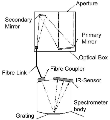
Reflected sunlight enters the Optical Box (O-box), see figure above. The O-box is located outside the spacecraft with the lunar surface in its field of view. The reflected light form the surface is concentrated and sent via a fiber cable to the instrument Sensor Head (SH) where it is split by the dispersive grating into its different wavelengths and adetected by the linear PDA IR-sensor consisting of 256 pixels.The dispersed light passes through a quartz body and a second order filter glued to the detector window. After passing this window, the light is absorbed by the photosensitive pixelated detectors, and the electrons collected in each pixel are sequentially read out as voltages to the ICU electronics after a defined and programmable integration time (exposure time).
Instrument Control Unit (ICU)
The voltages for each of the ISU pixels are digitized by a 16-bit ADC in the ICU. The data obtained are finally embedded in the data packages that are sent to the spacecraft’s mass memory for downloading to Earth.
To improve sensor stability, the PDA temperature is actively controlled by the ICU built-in control algorithm and a Peltier cooler and heater system, and excessive heat is radiated out to free space by the Radiator Unit (RU). The ICU also controls the power on/off of the SH so it only can be switched on when the temperature is not lower than -55 deg C. SH temperatures and other instruments’ essential temperatures are monitored and telemetered as Housekeeping data embedded in the instrument downlink data stream.

In addition to instrument control, the ICU electronics handle instrument commands through the 1553B MIL-BUS and the transfer of data packages to the spacecraft LVDS signal interface. The core of the ICU electronics design is based on the ACTEL RTAX FPGA technology (anti-fuse) where all the system logics and the processing capacities are implemented. An FPGA embedded microcontroller core with a watchdog circuit controls the electronics and ensures the instrument autonomy. The instrument default system program resides in the EEPROM/flash memory which enables the possibility of having stored the latest and optimized program and front setup parameters for the instrument. The RAM allows general purpose storage of programs and data. The watchdog works as an automatic power-on reset, starting the system in standby mode. An overview of the ICU interfaces to the ISU (J3) and to the spacraft (J1) is shown in the figure above.
The ICU is located inside the spacecraft, and therefore more protected from cosmic radiation and temperature effects.
Power supply unit (PSU)
The PSU contains the DC/DC converters, ON/OFF relays, the slow-start, and the EMC filtering which is connected to the spacecraft power bus. The power supply unit also contains the HK parameter signal conditioning circuits with MUXes and an ADC (16 bit) for the HK parameter monitoring.
The PSU is a custom designed DC/DC converter which powers the various parts of the electronics and contains the interfaces to the instrument health and temp monitoring sensors.
External Links
Max Planck Institute for Solar System Research
ISRO (Indian Space Research Organisation)
Team
Co-I and UiB Project Manager: Kjell Brønstad, Assoc. Professor
Staff Member: Kjetil Ullaland, Assoc. Professor
Technical Manager: Arne O. Solbeg, Senior Engineer
PhD Students: Olav Torheim, Yngve Skogseide